AND OPERATION
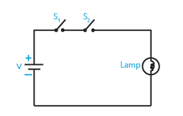
In order to understand the logic AND operation see the
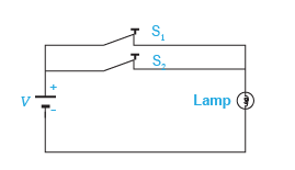
Fig. in which a lamp is connected to a battery using two
switches S1 and S2 connected in series considered as two
inputs.
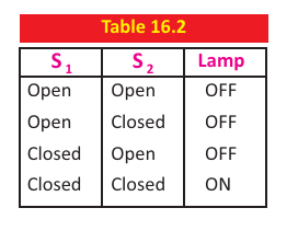
There are four possible states of these two switches
which are given below:
(i) When S1 and S2 are both open, the lamp is OFF.
(ii) When S1 is open but S2 closed, the lamp is OFF.
(iii) When S1 is closed but S2 open, the lamp is OFF.
(iv) When both S1 AND S2 are closed, the lamp is ON.
The four possible combinations of switches S1 and S2 are shown in the Table.
It is clear that when either of the switches (S1 or S2) or both are open, the lamp is OFF.
 When both switches are closed, the lamp is ON.
Symbol for AND operation is dot (.). Its Boolean expression is:
X = A . B and is read as “ X equals A AND B”.
Set of inputs and outputs in binary form is called truth table. In binary language, when either of the inputs or both the inputs are low (0), the output is low (0). When both the inputs are high (1), the output is high (1).
The truth table of AND operation is
shown in Table 2, where X represents the output.
Therefore, AND operation may be represented by switches connected in series, with each switch representing an input. When two switches are closed i.e., the inputs of the AND
operation are at logic '1', the output of the AND operation will be at logic '1'. But when two switches are open i.e., the inputs of AND operation are at logic '0', the output of AND operation
will be at logic '0'. For any other state of two switches (i.e., the input of AND operation), the output will be '0'.
The circuit which implements the AND operation is known as
AND gate. Its symbol is shown in Fig.
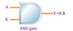
AND gate has two or more inputs and only one output. The value of output of
AND gate is always in accordance with the truth table of AND operation.
It means output of AND gate will be '1' only when all of its inputs are at logic '1', and for all other situations output of AND gate will be '0'.
OR OPERATION
In order to understand the logic OR operation see the circuit
shown in Fig.
A lamp is connected to a battery using
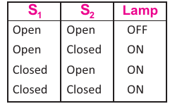
two switches S1 and S2 connected in parallel considered as two inputs. There are four possible states of these two switches which are given below:
(i) When S1 and S2 are open, the lamp is OFF.
(ii) When S1 is open and S2 closed, the lamp is ON.
(iii) When S1 is closed and S2 open, the lamp is ON
(iv) When both S1 and S2 are closed, the lamp is ON.
As evident from the circuit in Fig.,
the lamp will glow if at least one of the switches is closed. In the language of
Boolean algebra, we say the lamp will glow at least one of the values of S1 and S2 is at logic '1'.

Table describes all possible states of the switches for the
'OR' operation.
OR operation is represented by the symbol of plus (+).
 Boolean expression for OR operation is : X = A + B and is read as “ X equals A OR B”.
Truth table of OR operation is shown in
Table
An OR operation may be represented by switches
connected in parallel, since only one of these parallel
switches need to turn on in order to flow current in the
circuit.
Boolean expression for OR operation is : X = A + B and is read as “ X equals A OR B”.
Truth table of OR operation is shown in
Table
An OR operation may be represented by switches
connected in parallel, since only one of these parallel
switches need to turn on in order to flow current in the
circuit.
The electronic circuit which implements the OR operation is known as OR gate. Symbolically, OR gate is shown in Fig. It has two or more inputs and has only one output. The values of output of OR gate are always in accordance with the truth table of OR operation. It means:
The value of output of OR gate will be '1' when anyone of its inputs is at '1'. The output will be '0', when all inputs are at '0'.